Bulk loading
Hopper volume and refill method influence labour, line interruptions and component pressure.
Engineer the complete route—from bulk component loading to correctly orientated, demand-controlled presentation at your machine.
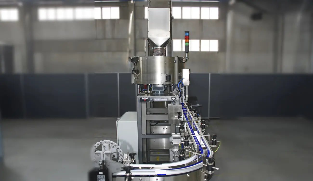
A high-speed parts feeder succeeds only when the component reaches the receiving process in the correct orientation, at the right spacing and at a rate the machine can actually consume.
We model the entire flow path so feeder capacity, accumulation and release cycle work together. This protects uptime and prevents a fast feeder from simply creating back pressure further downstream.
The right architecture follows from the slowest or least stable step. A structured review separates nominal cycle time from sustainable production performance.
Hopper volume and refill method influence labour, line interruptions and component pressure.
Stable metering into the centrifugal feeder prevents floods, starvation and excessive recirculation.
Tooling must accept the required state and return wrong states without destabilising correct parts.
Track geometry, transport method and lane count determine how accepted parts move away from the bowl.
The escapement and verification cycle must keep pace while preserving orientation and spacing.
Handshake logic allows the feeder to respond smoothly to normal pauses, full track and faults.
When one path cannot supply the required accepted rate, the solution may need a different presentation method—not simply more motor speed.
Improved separation, tooling and accumulation can unlock stable output with the least complexity.
Parallel tracks increase delivery capacity where component geometry and downstream interfaces allow.
Independent feeders can provide capacity, format separation or resilience for critical production.
Defined optical checks confirm visible orientation before release or reject incorrect parts.
Demand-controlled accumulation absorbs short stops without compressing or damaging components.
Recipes, sensors, alarms and upstream/downstream handshakes manage the system as one cell.
Terms such as “parts per minute” are useful only when the measurement boundary is clear. The agreed rate should state what counts as an accepted part, where it is counted, how long the test runs, which component samples are used and what operator intervention is normal.
Most receiving machines do not consume parts at a perfectly constant rate. Indexing, tool changes, quality checks and short stops create variation. Correctly sized accumulation prevents every momentary pause from stopping the feeder, while sensors avoid excessive back pressure or part damage.
A high-speed line needs planned responses to a full track, blocked escapement, empty hopper, open guard and emergency stop. Restart sequencing is just as important: the system should recover without flooding the bowl, releasing duplicate parts or creating an uncontrolled gap.
If the feeder handles a part family, production value depends on repeatable settings, format parts, recipe control and line clearance. A short headline rate does not compensate for slow or unreliable changeover.
Measure correctly orientated parts at the receiving interface under representative conditions—and record every intervention needed to sustain that result.
The limiting factor may be bulk replenishment, separation, orientation yield, track accumulation, escapement cycle time, inspection, downstream demand or fault recovery. The complete system must be measured.
No. Excessive speed can increase recirculation, collisions, marking and unstable outfeed. A better result may come from improved tooling, steadier bowl level, multiple lanes or a more capable downstream interface.
It can be possible, but the distribution, buffering, independent demand and failure modes need careful design. Separate lanes or feeders may provide better availability for some processes.
Run representative components for an agreed duration with normal replenishment and a realistic downstream simulation. Count accepted components at the discharge point and record interventions, rejects, stops and recovery.
Send a part photograph or drawing, required orientation, target sustained output and details of the receiving machine. We will define the right next step.
Share a photograph or drawing, required orientation and target rate. The Sortation Solutions team will help identify the strongest feeding route.