Caps & closures
Flat caps, screw closures, overcaps, dispensing closures, rings and similar moulded parts for capping or assembly.
From caps and closures to engineered mouldings: select the feeding principle from real component behaviour, output and orientation.
Centrifugal feeding can be highly effective when the component can be separated cleanly and its correct orientation can be recognised by robust tooling. Each application still needs representative trials.
Flat caps, screw closures, overcaps, dispensing closures, rings and similar moulded parts for capping or assembly.
Lightweight housings, inserts, clips and small moulded components where flash, static and cosmetic finish are assessed.
Suitable rigid components where controlled handling, cleanability, traceability and visible inspection may be required.
Clips, fasteners, washers, connectors and small engineered parts presented to assembly, insertion or inspection.
Insulators, housings, terminals and connector elements with defined orientation and careful interface control.
Suitable confectionery, wrapped items and rigid food products where material compatibility and hygiene are specified.
Formed metal parts, rings, fasteners and fittings where edge condition, oil and part-to-part contact are reviewed.
Dispensers, fitments, plugs, valves and closures orientated for downstream packaging machinery.
Small repeat-volume parts for assembly, counting, kitting, packaging or quality inspection.
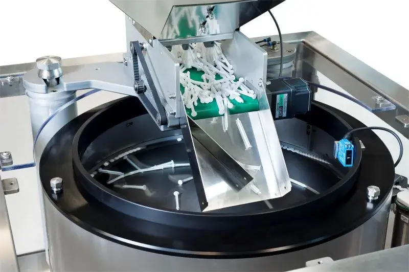
Feedability is not determined by dimensions alone. We consider how parts behave in a bulk mass, how reliably their orientation can be distinguished and what happens after repeated recirculation.
A short technical brief makes the first review faster and prevents critical component or interface information appearing late.
Which face, axis or feature must lead, and what tolerance can the next process accept?
Which sizes, colours, moulds, materials and revision states must share the system?
Is cosmetic marking, scratching, oil transfer, dust or static a process concern?
How many correctly orientated parts must be available per minute at the interface?
Does the part enter a nest, escapement, conveyor pocket, robot pickup or assembly tool?
What cleaning, material, guarding, noise, dust or controlled-area requirements apply?
Centrifugal feeders are frequently considered for closures because rigid moulded geometry can support rapid separation and orientation. The trial should include every cavity or supplier source, natural flash, colour and material variation, plus the condition in which closures arrive in production.
Lightweight plastic parts may respond well to rotary movement, but static, thin walls, interlocking features and cosmetic surfaces require attention. Disc surface, tooling material, air management and recirculation path are selected around this behaviour.
The scope can address suitable contact materials, enclosed construction, access for cleaning, controlled handling and defined inspection. The final design depends on the customer's quality, validation and environmental requirements; these are agreed at the start of the project.
Mass, sharp edges, residual oil and the potential for marking influence both feeder selection and tool wear. Representative production parts—not freshly selected samples—are important for a useful assessment.
A centrifugal bowl feeder is not automatically the right answer. Tangled components, very broad format ranges, fragile surfaces or complex orientations may favour vibratory, step, flexible or robotic feeding. Our role is to identify the strongest starting principle, not force every part into one technology.
Send a part photograph or drawing, required orientation, target sustained output and details of the receiving machine. We will define the right next step.
Share a photograph or drawing, required orientation and target rate. The Sortation Solutions team will help identify the strongest feeding route.